The Road Network
We use Lanelets to represent the scenario Road Network. It contains all topological information about the roads and their semantics, including lanes, road markings, traffic signs, traffic lights, crosswalks, intersections, and all relevant details that could affect the traffic. We decided to use Lanelets because of their compact and lightweight structure; the Geoscenario format follows a similar spirit itself. The Road Network is stored in a separate XML file to make replacements easy. However, a scenario can only be interpreted within the context of the Road Network. Thus, a Geoscenario must always be distributed with its associated Road Network file. The Lanelet file is defined inside the Global Config element.
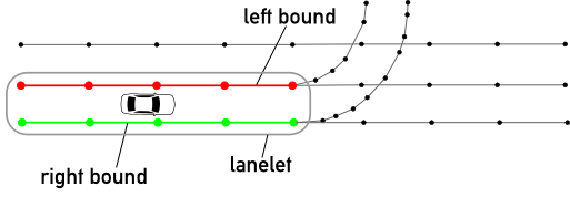
By definition, lanelets are “atomic, interconnected, drivable road segments geometrically represented by their left and right bounds” (Bender, et al. 2014). The bounds are encoded by an array of OSM nodes forming a polyline. Together, they compose the lanelet map. With lanes represented by road-segments with precise boundaries, Lanelets can be used to compose the Road Network of a scenario.
We recommend reading the Lanelet paper and checking their repository: https://ieeexplore.ieee.org/document/6856487 https://github.com/phbender/liblanelet
Locations
Locations are named points (or areas) of the road network that can be used to dynamic place other elements. This is specially useful when a scenario is built with mutation and automatic generation, which requires a base scenario with a certain degree of flexibility (boundaries or alternative points instead of pre-defined locations). Location elements can also be used to provide a more human-readable design, with key points of the road mapped to areas with meaningful names (for example, the approaching zone of an intersection). Locations are designed as an extra layer on top of the road network, and can be shared between scenarios. For example, location nodes can be placed as a collection of alternative starting points for a given vehicle and a scenario generation approach can search for the optimal point. Alternatively, this starting point can be designed as an area, and the optimization is bounded by this area.
<node id='-166757'>
    <tag k='gs' v='location' />
    <tag k='name' v='vehiclespawning_1' />
    <tag k='continuous' v='no' />
</node>
Location attributes:
| k | v | description |
|---|---|---|
| gs* | 'location' | GS role key |
| name* | string | A name for the location |
| continuous | bool | When a location is defined as a polyline (way), this attribute tells if the boundaries should be interpreted as continuous bounded area, or as a collection of discrete alternative points (nodes). |